
After postponing the job long enough, I finally got a little time to modify my WRX hatch for towing behind the motorhome. Little did I know this would take much longer than I originally had anticipated. By the time the car was complete and rolling again, about two weeks had passed. I spent the better part of two weekends plus some weeknights in between, estimating about 50 hours of work into this project.
I think the most difficult part about this was the custom nature of the job. The baseplate was semi-straightforward “bolt-on” work, but everything else (routing the Readybrake cable, emergency breakaway cable, wiring…) took quite a bit of problem solving and test-fit time. There are no car-specific instructions – only generic, which ate up time. Additionally, I wanted to do this right the first time, and make sure the front end of the car went back together in a way that all the systems worked without interference from anything.
Just deciding on my toad setup took some research in and of itself. If I had something more common to the motorhome “toad” community like a Honda CRV I would have had more resources available. But not many people are taking their Impreza WRX along for the ride behind the RV. Or at least if they are, no one is writing about it – so for that one other possible person who wants to bring along their “rocket hatch” on vacation, this is for you.
Sidebar – why this car? I’ve always been a geek for cars and when we bought our motorhome, it was about time for me to replace my aging Audi A4. Nothing in the car family was a “four wheels down” towable vehicle so I set out on a search for something to check that box but I could still enjoy for motoring fun. Apparently, the intersection of “toadable” cars and “lots of fun” cars leaves much to be desired. That landed me at a (used) 2007 Subaru Impreza WRX hatch (something very hard to find in non-teenager destroyed condition). Manual transmission for towing compatibility, four door hatch to carry the family and the dog when needed, AWD for whenever it might be necessary, and close to 300hp (courtesy of a COBB stage 2 tune and Daddy’s SCP 3″ exhaust) for whenever that – err – might be necessary as well. It’s so quick the kids call it “Lightning” after Lightning McQueen from CARS 🙂
Back to the choice of parts – I decided for the ReadyBrake approach instead of a floor-mounted “R2D2” looking system which activates the brake pedal. I liked the simplicity of a cable and not having anything to remove / re-install inside the car when I needed to tow it. Additionally, I went for a completely separate lighting circuit instead of tapping into the car’s electrical system.
Here is a list of everything I installed to get my WRX up and running for “Toad Duty:”
- ReadyBrake braking system receiver – this system works your brake pedal based on a “surge brake” principle
- ReadyStop emergency breakaway kit – activates (i.e. yanks) your brake pedal should the car become disconnected from the motorhome
- RVi Brake towed vehicle battery charger – keeps your car battery charged via the motorhome
- Curt 4-way connector mounting bracket – I used this to mount the ready brake cable and the “hold” mechanism for the emergency stop cable
- Curt electrical connector mounting bracket (2) – I used two of these: one to mount the 4-way for the cable (above) and the other to mount the 6-way electrical connector
- Blue Ox BX8869 Bulb and Socket Tail light wiring kit – this allows you to avoid tapping into the car’s lighting system with diodes, by instead installing separate bulbs
- Curt 6-way connector mounting bracket – to mount the 6-way receptacle
- Blue Ox BX88206 Coiled cable – this connects the motorhome to the tow vehicle (it also came with a 6-way receptacle)
- Roadmaster XL Baseplate kit (916-1) – the bracket mounted to the car frame to provide mounting points for the tow bar
- Roadmaster Falcon All-Terrain tow bar – tow bar to “hitch” the car to the motorhome receiver via the baseplate mounting points
I initially had planned to buy a ReadyBrute tow bar (which integrated the ready brake into a tow bar) but found next to nothing available on the used market. On top of that the Roadmaster baseplate was the only one available with removable arms (Blue Ox only makes one with fixed arms). Finally, to use a ReadyBrute with a Roadmaster XL baseplate would have meant additional costs in adapters – so when I found a good condition Falcon All-Terrain on Craigslist and a ReadyBrake receiver on ebay (at the same time) I jumped at the chance to save $$$ and still meet my needs.
For installation, I additionally needed quite a disperse selection of tools and materials from my garage to get this done. Multimeter, extra wiring, butt connectors / tap connectors (all-weather recommended), shrink wrap, electrical tape, wire strippers, tin snips, Dremel tool, electric drill and bits from 1/8″ up to 1/2″, workbench vise, gloss black spray paint, silicone, wire loom, test light, all sorts of sockets / wrenches, flashlight / headlamp, mirror tool for hard to reach places…
First up was the baseplate install. Later I would learn this was the “easiest” part of the job. However Roadmaster needs to make note of a few things:
- The physical mounting points are the same from 2004-2007 but the front bodywork is slightly different between 04/05 and 06/07. Roadmaster only supplies instructions from the 04/05 perspective. So many details about fastener removal did not apply, and I had to figure out on my own (and Google) how to remove the grille, bumper, etc. Not a show stopper but annoying.
- The “backing plates” they provide for bolting the baseplate at lower left and right had holes that were too small for the included bolts. Another annoying slowdown. I had to clamp these into my vice and enlarge the holes. These were obviously stamped parts from some stock thickness … Roadmaster, your supplier should update these dimensions.
- Back to the 04/05 vs. 06/07 differences, all the instructions about trimming the front bumper to clear the baseplate were “not applicable.” That took some trial and error to get right.
-

- On jack stands ready to start the install
-

- C-clamps help keep the baseplate in position
-

- Wrong ID on the fastener “backing” plates from Roadmaster
-

- Finally got the lower bolts installed
-

- Ready to modify the bumper
After installing the baseplate I spent some time trimming the front bumper. Here are some key pictures of the modifications. Each side in the lower radiator opening needs to be enlarged for the receivers, and the center support needs to be trimmed at the back for the “crossbar” of the baseplate.
-

- Trimming for the baseplate receiver
-

- Trimming for the baseplate crossbar
At this point I thought I was more than halfway, but in fact I was probably only about a third. The wiring and ReadyBrake cable install took a significant amount of time. In retrospect I wonder if I might have gone with a diode system instead, or if I could have come up with a better way to drill holes in the tail light housings. Even though I held a vacuum the best I could at the drill bit, I still ended up with plastic “dust” inside the lens.
I also decided against routing the wires through the interior of the car, and went underneath instead. I wasn’t in the mood for removing significant parts of the interior (and probably damage half of the 9 year old plastic parts and retaining clips) and since I saw a clear path underneath for the wires, I went for that. Looking back I can see the pros/cons to each and I might have done it differently, but as long as this works I’ll leave it alone.
-

- Thankfully I had plenty of wire etc for the job
-

- Hole drilled in the housing – make sure it’s where you want it!
-

- Bulb installed with silicone. If this burns out and has to be replaced, it won’t be easy
-

- A little dust in the lens
-

- Dropping wires from lights to route underneath the drivers side of the car
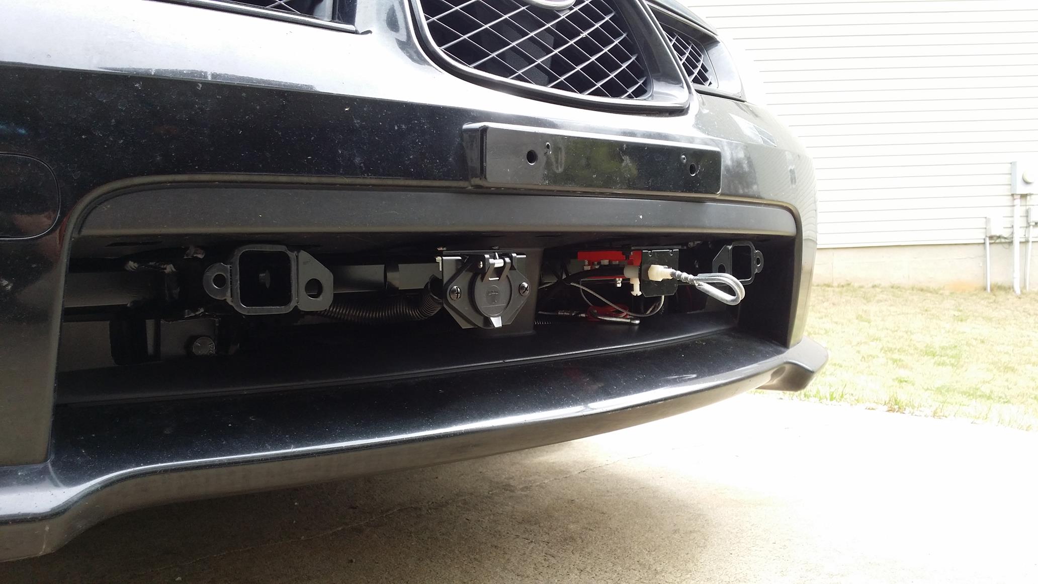
Once I got the wires routed to the front of the car, I left it as-is until I could figure out where everything else would exit from the bumper. I decided on the Curt brackets in two places, either side of center; left for the 6-way and right for the Readybrake cable. I also got the rattle can out and spray painted the bolts to match the rest (black).
-

- Mock-up for the Readybrake cable
-

- Decided on bracket locations
Back to the wiring, I needed to finalize the location of the charge module and double-check each pin in the “umbilical” when connected to the motorhome so I would know where to wire the 6-way at the car side. From experience, I’ve seen the +12v wired differently and wanted to confirm.
Additionally I needed to find the wire to tap into for the brake light switch. The Readybrake comes with an LED light and wiring to connect to the receiver, the intent being that one would install the LED on the motorhome dash to know when the toad is braking. I liked the concept, but that would only tell me that the Readybrake lever was moving, not that the toad was actually braking. I wanted to install two LEDs – one to know about the lever, the other to know the status of the toad’s brake pedal. This way I should know if things are / are not working the way I want. (I don’t claim to have thought of this first, but gleaned it from tips on rv.net and the Tiffin forums). I used the one spare pin in the 6-way to feed this signal back to the RV.
Once I had confirmed the right pins and wires I needed, I completed the 6-way wiring with heat shrink and then dielectric grease inside the boot. I’ve read about corrosion problems here and hopefully this can prevent / delay the issue.
-

- RVi brake battery charger installed
-

- Confirming the +12v pin when connected to the RV
-

- 2007 Subaru Impreza WRX brake light wire – black/white
-

- Test fit the bumper with the wire loom (carrying the 6-way wires) in place
-

- Finishing up the 6-way
Getting closer – time to finalize the Readybrake cable and the breakaway cable attachment to the brake pedal. I wish I would have gotten more pictures of what I went through to get these cables installed – the most difficult part of the entire job was getting the right holes in the right place in the firewall, and then getting the fitting and the cables through the firewall – blind!
Some tips for getting the holes located:
- Hopefully you can see from one of the pictures where I ended up with the fitting for the Readybrake cable. I had to drill two holes after the first – while seemingly in the right spot – had a bad angle for pulling on the brake pedal.
- Underneath the car, when trying to get the fitting through the hole you’ve drilled, there is no way to see it directly. I had to use a combination of headlamp and mirror (on an extension) and a little “luck.” I was surprised that I was able to get this into place – twice. If it didn’t work I was going to have to resort to some type of “fish wire” setup.
- Be conscious of how your feet are positioned with respect to the pedals and the cable bracket on the pedal arm. I didn’t think about this and (see the first picture) realized when I sat in the car that my clutch foot was also activating the brakes because of the bracket location. I shifted the cable and bracket to the right side of the arm and had no more interference problems.
To add to the “fun” – the plate that ReadyBrake supplied for attaching the cables at the brake pedal arm was missing a cable hole. They specifically say in their instructions that you can use this plate to install both the ReadyBrake pedal and the emergency stop pedal – and show a plate with four holes. I made a workaround with cable clamps but another source of frustration.
Even MORE “fun” – the red “module” – part of the emergency brake system which allows cable travel in one direction but not the other – had the cable installed the wrong way from the factory. Thankfully I discovered this before final installation, but pulling it out of the module and then reinstalling was a bear. It won’t simply thread through, instead you have to remove the threaded “exit” fitting with a wrench and then work the cable through this fitting while pressing it into the “release” position.
-

- ReadyBrake plate missing one cable hole
-

- Bad positioning of the cable plate
-

- Corrected positioning – also note the cable fitting location at the firewall
-
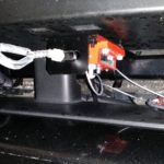
- Readybrake cable and e-stop cable installed
Wow – that took a REALLY long time! I got everything buttoned up, re-confirmed the function of wires / cables the best I could and then installed the front bumper and the gravel shield. You’ll end up with a few extra plastic fasteners than what you started with – the lower baseplate braces cover the holes that had been used for them.
I’m somewhat satisfied with the results and glad that I took the time to paint over the bright silver fasteners. I would have liked to recess the Readybrake cable loop underneath the bumper, but with the radiator directly behind I didn’t want to (possibly) compromise the cable housing with a tighter radius.
Another note – if you notice these things (like me) there is a slight resistance in the action of pressing / releasing the brake pedal due to the Readybrake cable (friction in the housing). I only notice this at stoplights but it doesn’t affect anything like heel/toe driving, so all’s good with that.


Lastly I did some test fitting of the arms for the tow bar and the tow bar cross brace. I realized I got lucky here because I didn’t think ahead about having clearance for the pins to install in the arms from the side of each receiver. Thankfully I left enough room vs the 6-way and the cable brackets I installed! Then I measured the height of the arms vs the RV receiver height to get an idea of the drop adapter I would need, and tested the wiring with the car connected to the RV via the Blue Ox cable. Brakes, turn signals, charging battery – all systems check!
-

- Testing out the tow bar cross brace
-

- Measuring for a drop hitch
Next up is to finish wiring on the motorhome side (LED lights for the Readybrake lever and toad brake pedal switch) and then a test tow!
Nice! Way to use that spare lead from the 6-pin to send the brake signal!
One thing that’s not apparent in the photos: is your path from emergency block to the brake pedal going to result in crushing your radiator? I ASSUME given everything else done so well and thoughtfully that you’ve validated the path, but also just want to make sure!
Great question Brian – I should have taken a photo of the routing. It took me awhile to figure out the various compromises. I wanted to have a straight shot from the firewall, along the frame rail and then out the front but there were too many other obstructions, and I found mounting options for the “red module” very lacking. I ended up routing as above (firewall/frame rail) and then under the front subframe (which would protect the radiator from the cable) and out the front as seen in the pictures. It wasn’t ideal, but I did a couple “light pull” tests and was fairly comfortable that nothing critical on the car would get damaged – if anything a couple scrapes on the subframe and possibly fraying of the e-cable itself. I hope it never has to be used, but if so I think the car won’t be left disabled from it.
Perfect. I figured you’d have it sorted, but had to ask.
Terrific job of documenting this setup!
Thank you Frank!